General Case
Imagine a client comes to you and gives detail about the requirements. Suppose his requirements are
Living Room 3 x 3.6
Kitchen 2.7 x 3.6
Two Bed Rooms 3.9 x 2.1
Bath 2.1 x 2.1
Imagine a tool that would take these inputs and generate a plan automatically. Making that tool is the aim of this post
Let me demonstrate the use of the tool that I made
Load the given requirements in an excel file as shown.

Now go to the Dynamo file and link the path of this file to the node given.

Now what this dynamo file would do in Revit is , it produces all the required rooms in to an instances of space family. The space family is designed in a generic model with parameters of height, length, width and name.


So to start with planning we can start by cascading the required rooms like how we arrange puzzle pieces into the total area.

Finally use wall by face to place wall instances along the 3D faces. Once these faces have been used to make wall the the 3D family can be deleted. Use wall opening tool to create various wall opening.

So within couple of minutes we have a working model in Revit with which we can start working.
The Code

So the basic idea of this code is:
- Take data from excel sheet.
- Sort it so that lists under different headings .
- From this list count the number of instances required.
- Then places a similar kind of instances .
- Provide sufficient space between the instances.
- Then take these instances and manipulate the parameters in them.
The above code was used to make the plan . The green colored module on the left uses the excel sheet to read data.
 |
SI 1 |
The purple colored group take these data and sort. The top node group sorts and adds an unique number index taking into account the number of times a instance can be used.
The node group below that multiplies the width with quantity to get the number of width instances.
Similarly the group below it does the same thing to the Length.
 |
SI 2 |
 |
SI 3 |
 |
SI 4 |
The fourth does the above function but to the all parameters in the excel files. That is, to multiply by the quantity so that new instances are repeated.
 |
SI 5 |
Once the sorting is done in this way,a integer slider control is introduced to manage the the distance between the space instances. Changing the slider would increase or decrease the space between instances so that they can used properly.In this node the space between the instances is governed by parameters Width and Length.
Once this is done. The program uses the points generated and counts the number of points by using a math node. It uses the space between points created using the slider in the previous nodes so that sufficient space is available to avoid intersecting of elements.
 |
SI 6 |
Once this is done. The program uses the points generated and counts the number of points by using a math node. It uses the space between points created using the slider in the previous nodes so that sufficient space is available to avoid intersecting of elements.
 |
SI 7 |
These points are used to create points using Point. Add Node. Family Type has to be selected which in this case is Space Family. So number of instances as required by the user are created at this juncture but those instances are all same . So a node group has to be created so that it can manipulate the parameters in the instances already placed.
Hence the final group of nodes do this by using Element. SetByParmaterName node. These nodes manipulate Length, Width, Height and Name parameters.
Hence at this point the space instances are created and stacked one after the other. Now simple cascading operation using move tool can used to arrange these space.
As said before, the Wall-By-Face can be used to create walls. Then the space family can be deleted. Wall opening or doors can be added to get a working 3D model in Revit.

Counts number of times each unique item is in a list. For example a list with following values { 0,1,2,2,3,3,3}, this node will tell you that the frequency of 0 and 1 is 1, for 2 and 3 is 2.
To use this node two other nodes have to be added. They are show in the following figures.


 |
SI 8 |
Hence at this point the space instances are created and stacked one after the other. Now simple cascading operation using move tool can used to arrange these space.
As said before, the Wall-By-Face can be used to create walls. Then the space family can be deleted. Wall opening or doors can be added to get a working 3D model in Revit.
LunchBox and Clockwork
Some of the nodes in this program were used from Lunchbox ( 2016.11.8 8Nov 2016 Version). Those nodes were;
LunchBox. Mass Addition
THis nodes returns the total value of a list of numbers. It is used as a recursive function.
Clockwork Nodes.
Clockwork is a package which is a collection of useful nodes. It is sub-program int eh main program.. It has to be loaded in the same folder as the main dynamo file. When loaded and called for, it returns the values into the main program from sub program. Following clockwork nodes were used in the present project
List.CountOccurences
To use this node two other nodes have to be added. They are show in the following figures.

List.SublistLengths

TurnIntoList
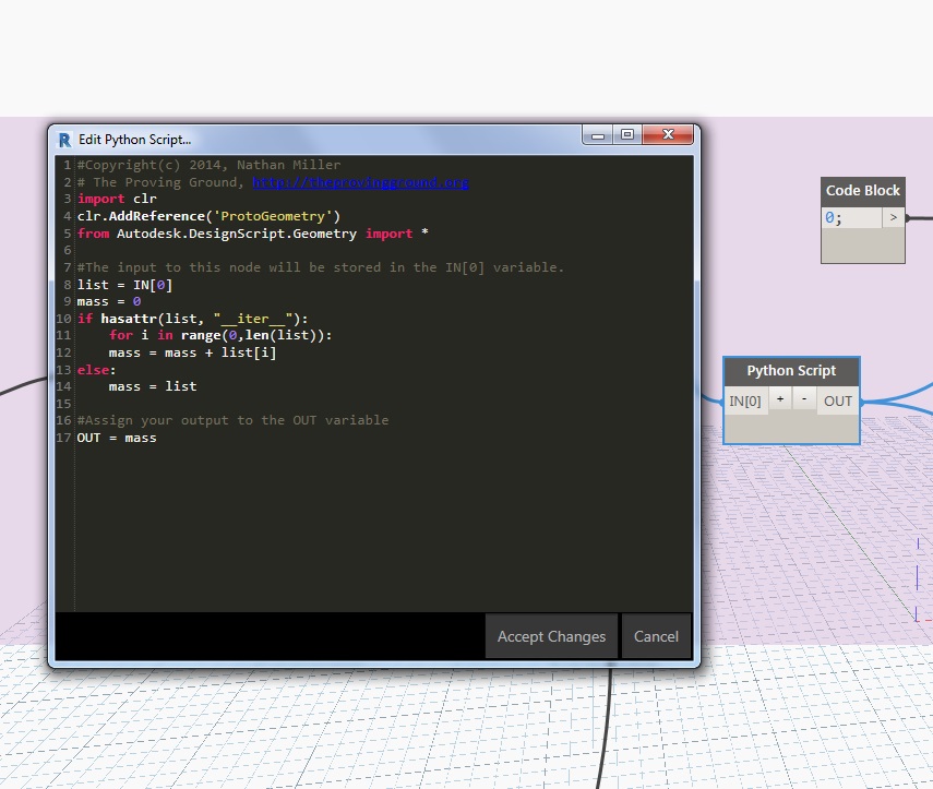
Python Script/Node
A small python script had to be used which was just a replacement for LunchBox Mass Addition node. As the Mass. Addition node was used as a recursive function, the python script from this node was copied to do this. This was done so that LuchBox need not be installed on every computer this program runs, but due to accumulation of errors it was thought to go with the installation of LunchBox.
Hanoi Museum Project 1
The same code was used to make plan for the Hanoi Museum which was created in the previous project.
These are the rendering from that project.


Uses:
- In the initial planning stage this tool enables a simple manipulation in excel sheet data to change the plan in Revit file. Hence it eases the effort required in scheduling.
- Many different options of floor plans can be generated so that a better decision can be take.
- The space instances can be printed in 3D printer and can be arranged as models for presentations.
- It eases the documentation part of the planning as working plans and there excel sheet data can be quickly generated.
Future Development
- Adjacency studies can be applied to this model. In which a particular instance is not desired to be placed beside another instance. For example Restrooms placed beside kitchen. These kind of constraints can be developed in Dynamo
- Optimo can be used to optimize the various factors like maximizing the space, minimizing the walls. minimizing the walk-run in a building with given set of constraints like the plot size etc.
Concluding Remarks
This tool has lot of scope to improve efficiency in an Architectural Firm. especially at the planning stage looking at the ease with which plans are generated. This code gives sufficient control over the project allowing lot of tweaks from the used end to achieve a efficient plan design.
References:
1. Martin K. The Space Planning Data Cycle with Dynamo. http://dynamobimorg. 2015. Available at: http://dynamobim.org/space-planning-data-cycle/. Accessed November 29, 2016.
No comments:
Post a Comment